I2C data is ‘open drain’.
I spent way too long on figuring out this one. And it feels like one of those issues that are certain to come back and haunt at some point. (Unless I now jinx it by writing all this down).
So. While trying to do some I2C communication using libOpenCM3
on a STM32 discovery board
that libOpenCM3 did not have an I2C example for, I run into this:
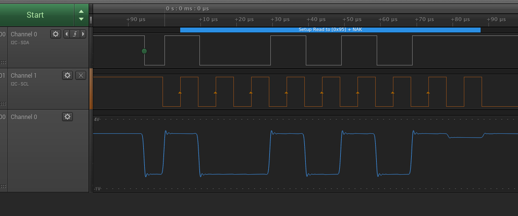
Here the STM32 writes the address byte to I2C, and gets a NACK (at about 80us). (An ACK would be sent by the slave device after receiving a byte by it pulling down the data line for the clock cycle following the transmitted byte.)
Looking at the blue oscilloscope line it is clear that something tries to pull the data line down, but fails.
STM GPIOs
The trick is to RTFM.
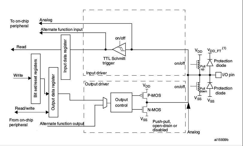 Schematic of a STM32 GPIO pin (image from STM, RM0383).
In order to have the I2C peripheral’s lines visible on the pin, one must:
- select the alternate function that is routed to the i2c peripheral (see datasheet for the table of alternate functions)
- configure the output control to open drain
- configure pull up (if there are not external pull-ups)
The problem was that output control has push-pull as default (which I didn’t notice and override). In this mode both the P-MOS and N-MOS are used, i.e. the output is always connected to either Vdd or GND.
Whereas in open drain mode (quoting the fine RM) “A “0” in the Output register activates the N-MOS whereas a “1” in the Output register leaves the port in Hi-Z (the P-MOS is never activated)”.
For the ACK/NACK, the I2C peripheral leaves the data line into ‘1’, where only the pull-up resistor pulls the line up - when in open drain mode…
Or in libOpenCM3 terms:
rcc_periph_clock_enable(RCC_GPIOB);
gpio_set_af(GPIOB, GPIO_AF4, GPIO9);
gpio_set_output_options(GPIOB, GPIO_OTYPE_OD, GPIO_OSPEED_25MHZ, GPIO9);
gpio_mode_setup(GPIOB, GPIO_MODE_AF, GPIO_PUPD_PULLUP, GPIO9);